
 EN
EN
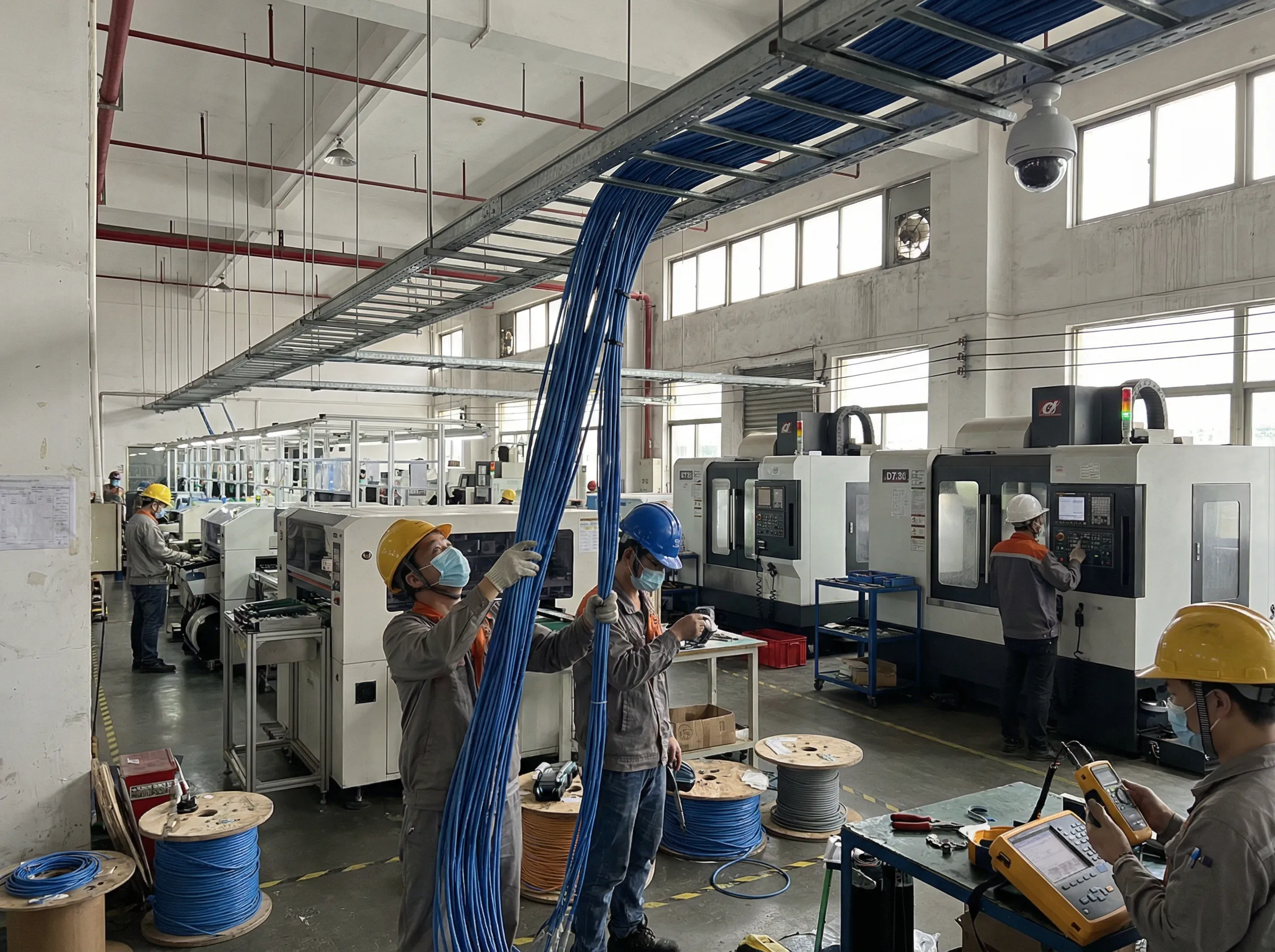
Deploying bulk fiber optic and structured copper cabling across a university campus, corporate park, or large institutional facility is vastly different from installing localized runs in a single server room or small office. Campus environments require pulling high-fiber-count backbones across hundreds of meters, navigating underground conduits, inter-building risers, and high-density distribution frames under tight construction deadlines.
A successful campus network deployment relies heavily on meticulous pre-deployment engineering, rigorous tension and route management, structured termination workflows, and multi-stage certification testing.
1. Campus Infrastructure Scale: Structural and Physical Challenges
In campus backbone deployments, small installation errors multiply exponentially across long cable distances. Understanding the physical dynamics and environmental constraints is essential before beginning any major cable pull.
Key Physical & Environmental Factors:
-
Tension and Mechanical Stress: Pulling high-density cables (such as 144-fiber or 288-fiber loose-tube cables) over runs exceeding 300 to 500 meters introduces massive pulling tension. Exceeding the maximum tensile strength rating causes microscopic glass fractures (microbends and macrobends), leading to severe optical attenuation and long-term signal degradation.
-
Complex Multi-Environment Routing: A single campus backbone run typically traverses diverse environments:
-
Underground Ducts & Manholes: Subject to water accumulation, dirt, debris, freezing temperatures, and physical crush risks.
-
Vertical Building Risers: Require specialized fire-rated jackets (OFNR/OFNP) and vertical strain-relief supports to prevent cable weight from stretching the fibers over time.
-
Overhead Trays & Plenums: Must comply with strict plenum fire codes and maintain proper distance from high-voltage power lines to avoid interference and safety hazards.
-
-
Conduit Clearance and Fill Ratios: Miscalculating conduit fill ratios or attempting to pull through partially crushed or obstructed underground ducts leads to stuck cables, crushed jackets, and costly civil excavation repairs.
2. Pre-Deployment Engineering: Site Surveys, Routing, and Labeling
Execution efficiency depends directly on the thoroughness of pre-deployment planning. Over seventy percent of project success is determined before the first cable reel is unsealed.
Critical Pre-Deployment Milestones:
-
Comprehensive Pathway Survey: Every meter of the planned path must be physically inspected. Technicians must verify conduit integrity using mandrel testing, measure exact distances, record all bend angles (ensuring cumulative bends between pull boxes do not exceed 360 degrees), and locate all intermediate junction boxes.
-
Detailed Cable Routing Schematic: A fully documented cabling blueprint must be shared across civil contractors, IT engineering teams, and facilities management. This diagram maps out exact reel lengths, splice locations, slack loops, and entrance facility patch panels.
-
Standardized Labeling Schema: Every cable sheath, innerduct, splice tray, and patch panel port must receive durable, standardized labels at both ends prior to and immediately following the pull. Clear labeling prevents catastrophic tracing errors during future maintenance and troubleshooting.
3. Selecting Cable Media and Termination Architectures
Designing a flexible, future-proof campus network requires selecting the appropriate cable constructions for specific segments and choosing the right termination methodology.
Outdoor Backbone vs. Indoor Horizontal Media
-
Outdoor Loose-Tube Fiber Cables: Designed for inter-building underground conduits and aerial spans. They feature gel-filled or dry-water-blocking tapes that prevent moisture ingress and allow individual buffer tubes to float freely, absorbing expansion and contraction caused by seasonal temperature shifts.
-
Indoor Tight-Buffered Fiber Cables: Optimized for intra-building distribution and vertical risers. They feature a flexible, flame-retardant outer jacket with 900-micron buffered fibers that are easy to fan out, route, and terminate directly inside telecommunications enclosures.
-
Category 6A / Cat8 Structured Copper: Deployed for horizontal runs from telecommunication rooms to desktop outlets, wireless access points (WAPs), security cameras, and building automation systems requiring high-bandwidth Power over Ethernet (PoE++).
Termination Strategy: Pre-Terminated vs. Field Splicing
-
Factory Pre-Terminated Assemblies: Ideal for predictable, direct building-to-building links. They arrive 100 percent factory-tested, drastically reducing field installation labor and eliminating contamination risks associated with on-site termination.
-
Field Fusion Splicing: Essential for complex routes with unpredictable pull distances or tight conduit restrictions where pull eyes cannot pass. Fusion splicing offers the lowest insertion loss (typically under 0.05 dB per splice) and superior mechanical reliability.
4. Multi-Stage Quality Control and Operational Testing Matrix
To guarantee that installed links support high-speed migration (40G, 100G, and 400G Ethernet), testing must occur continuously throughout the installation process rather than only at final sign-off.
The Three-Stage Testing Protocol:
-
On-Reel Testing (Pre-Installation): Test all fiber reels with an Optical Time-Domain Reflectometer (OTDR) while still on the shipping spool to verify that no internal manufacturing or transit damage exists before pulling.
-
Post-Pull Testing (Before Termination): Conduct continuity and OTDR checks immediately after pulling cables through conduits to confirm that pulling tension did not cause micro-fractures or jacket damage.
-
Final Link Certification: Perform Tier 1 (Optical Loss Test Set) and Tier 2 (OTDR trace analysis) certification on all completed channels to document end-to-end insertion loss, return loss, splice quality, and overall length.
Operational Troubleshooting & Prevention Guide
| Observed Issue | Probable Root Cause | Corrective & Preventive Action |
| High insertion loss / local OTDR spike | Microbend caused by excessive pulling tension or tight bend radius | Inspect cable pathway for pinch points; maintain minimum dynamic bend radius (20x outer diameter during pull) |
| High attenuation at 1550nm vs 1310nm | Cable pinching or crushing inside conduit or tray | Locate stress point using OTDR; relieve mechanical pressure or re-pull damaged segment |
| Complete signal loss / optical break | Structural fracture from exceeding tensile limit or conduit crush | Excavate/repair damaged conduit; perform fusion splice repair or execute a fresh cable pull |
| Intermittent link drop / high BER | Contaminated connector end-faces or improperly seated modules | Inspect all fiber end-faces with a digital inspection scope; clean with lint-free wipes and 99% IPA alcohol |