
 EN
EN
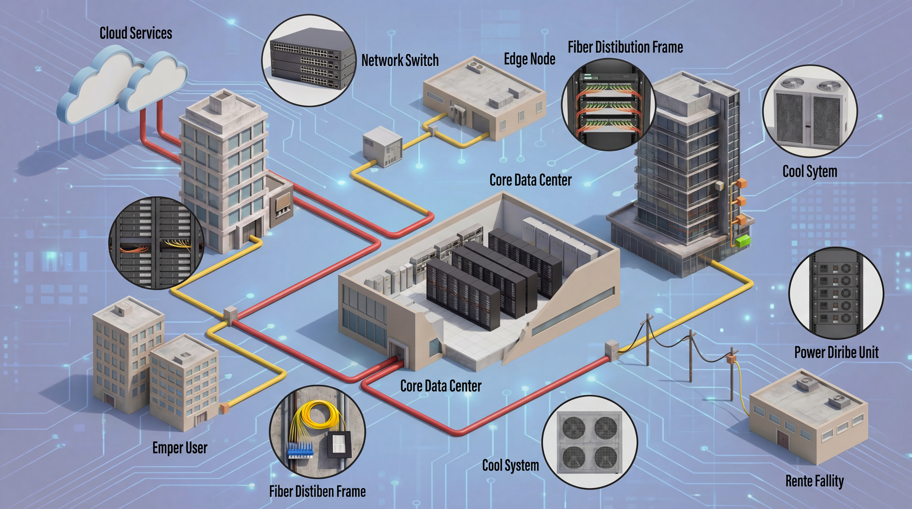
High-density data center environments present severe mechanical and spatial challenges for network cabling. As rack densities increase with switch port counts climbing to 48 or 64 ports per rack unit (RU), traditional thick, rigid copper patch cords create cable congestion, restrict cooling airflow, and suffer from conductor fatigue due to tight bend radii.
Deploying high-flex, reduced-diameter Ethernet patch cables (typically utilizing 28 AWG or 30 AWG stranded conductors) solves these physical bottlenecks, protects link integrity during routine maintenance, and optimizes rack thermal management.
1. Physical Engineering: Standard vs. High-Flex Patch Cables
The difference between standard patch cables and high-flex patch cords lies in the internal conductor gauge, stranding count, outer jacket compound, and strain-relief boot engineering.
Comparative Engineering Specifications
| Parameter | Standard Patch Cable (24 AWG) | High-Flex Patch Cable (28 AWG) | Ultra High-Flex Patch Cable (30 AWG) |
| Conductor Gauge | 24 AWG Solid / Stranded | 28 AWG Fine-Stranded | 30 AWG Ultra-Fine Stranded |
| Outer Diameter (OD) | ~5.8 mm – 6.5 mm | ~3.8 mm – 4.2 mm | ~2.8 mm – 3.2 mm |
| Bundle Volume Reduction | Baseline (100%) | ~33% to 50% Reduction | Up to 60% Reduction |
| Minimum Bend Radius | 4x to 8x Cable OD (~25mm–50mm) | 4x Cable OD (~15mm–16mm) | 4x Cable OD (~11mm–12mm) |
| Flex Life Cycles | ~1,000 to 3,000 cycles | 10,000+ dynamic flex cycles | 20,000+ dynamic flex cycles |
| PoE Support Threshold | Up to 90W (PoE++ / Type 4) | Up to 60W–90W (Derating required) | Up to 30W–60W (Smaller bundle limit) |
2. Key Structural Components of High-Flex Cables
-
Fine-Stranded Conductors: Standard cables use larger, stiffer copper strands that develop micro-fractures under repeated bending. High-flex cables employ dozens of ultra-fine copper strands twisted together. This allows individual strands to slide past one another when flexed, absorbing mechanical stress without fracturing.
-
Low-Memory Elastomeric Jackets: Standard PVC jackets exhibit a "memory effect," holding bends and kinking when rerouted. High-flex cables use flexible thermoplastic elastomeric (TPE) or specialized highly flexible PVC compounds that resist memory retention and maintain elasticity.
-
Flex-Relief Snagless Boots: The junction where the cable enters the RJ45 connector is the primary point of stress concentration. High-flex patch cords feature integrated, ultra-flexible strain-relief boots with a snagless latch guard, preventing latch breakage during moves, adds, and changes (MACs).
3. Thermal and Spatial Benefits in High-Density Racks
In modern enterprise server racks and top-of-rack (ToR) switch deployments, cable mass directly impacts thermodynamic efficiency.
Standard 24 AWG Cable Bundle (Massive Airflow Obstruction): > Large cable diameter occupies critical rack space, blocking up to 50% of rear exhaust airflow.
High-Flex 28 AWG Cable Bundle (Optimized Air Clearance): > Reduced diameter frees up horizontal and vertical cable channels, restoring up to 30%+ free air circulation.
Operational Advantages
-
Restored Exhaust Airflow: Thinner 28 AWG high-flex cable bundles occupy up to 50% less physical volume in horizontal cable managers and vertical zero-U pathways, reducing thermal resistance and HVAC cooling power requirements.
-
Simplified Maintenance & Traceability: Technicians can easily reach individual switch ports without disturbing adjacent connections, eliminating accidental link drops during live port maintenance.
-
Reduced Weight Burden on Interfaces: Lighter cable mass reduces gravitational leverage strain on switch ports, patch panel jacks, and server NIC interfaces.
4. Technical Standards and Performance Considerations
While high-flex 28 AWG patch cables offer significant physical advantages, network engineers must observe specific TIA and ISO standards regarding channel reach and Power over Ethernet (PoE) deployment.
TIA-568.2-D Standard Guidelines
The ANSI/TIA-568.2-D standard officially recognizes 28 AWG patch cords, subject to specific deployment rules:
-
Increased Attenuation (Derating): Because thinner 28 AWG conductors exhibit higher DC resistance and attenuation than standard 24 AWG copper, higher attenuation de-rating factors must be applied.
-
Maximum Channel Distance: The maximum recommended channel length (horizontal cable + patch cords) is reduced when using 28 AWG patch cords. For example, if using 10 meters of 28 AWG patch cords, the maximum permanent horizontal link must be reduced accordingly to maintain the 100-meter channel performance budget.
-
Power over Ethernet (PoE) Bundle Limits: Due to thermal buildup in smaller wire gauges, TIA guidelines mandate smaller maximum bundle sizes (typically 12 to 24 cables per bundle) when delivering higher wattage PoE (such as 60W or 90W IEEE 802.3bt Type 3/4) to prevent overheating.