Fiber Optic Splitter Terminal Box | IP65 FTTH Enclosure

All Categories
Efficient Fiber Splitting and Terminal Management

Efficient Fiber Splitting and Terminal Management

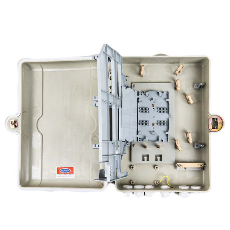
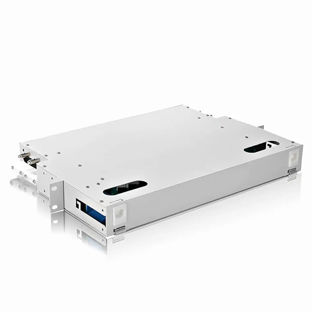
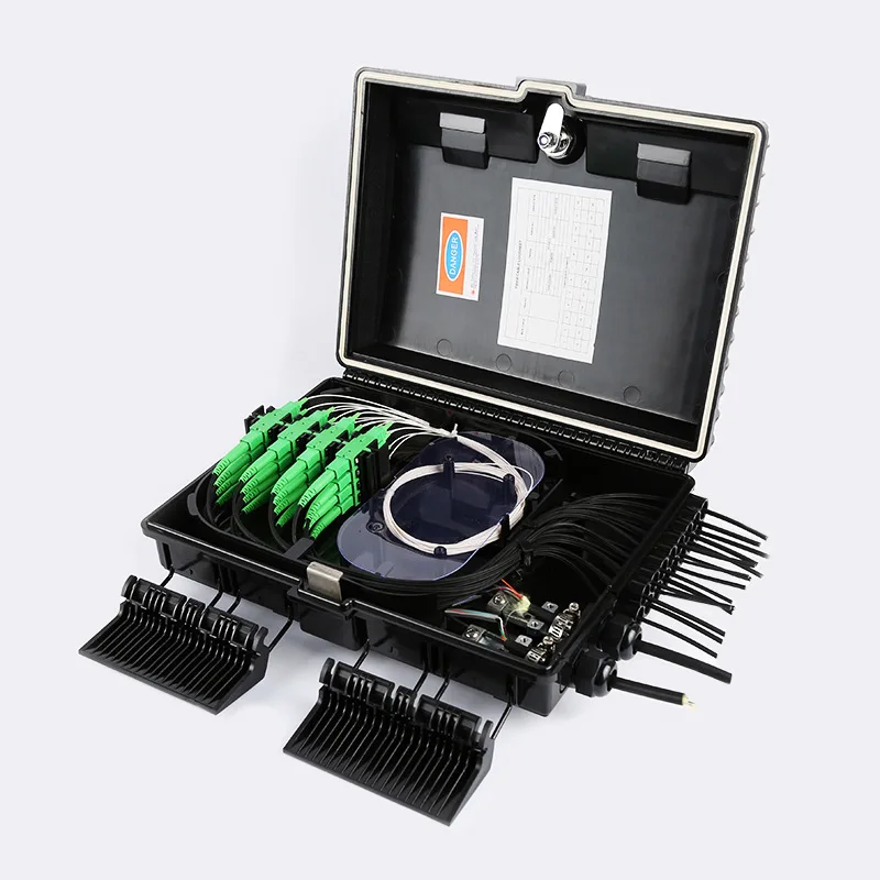
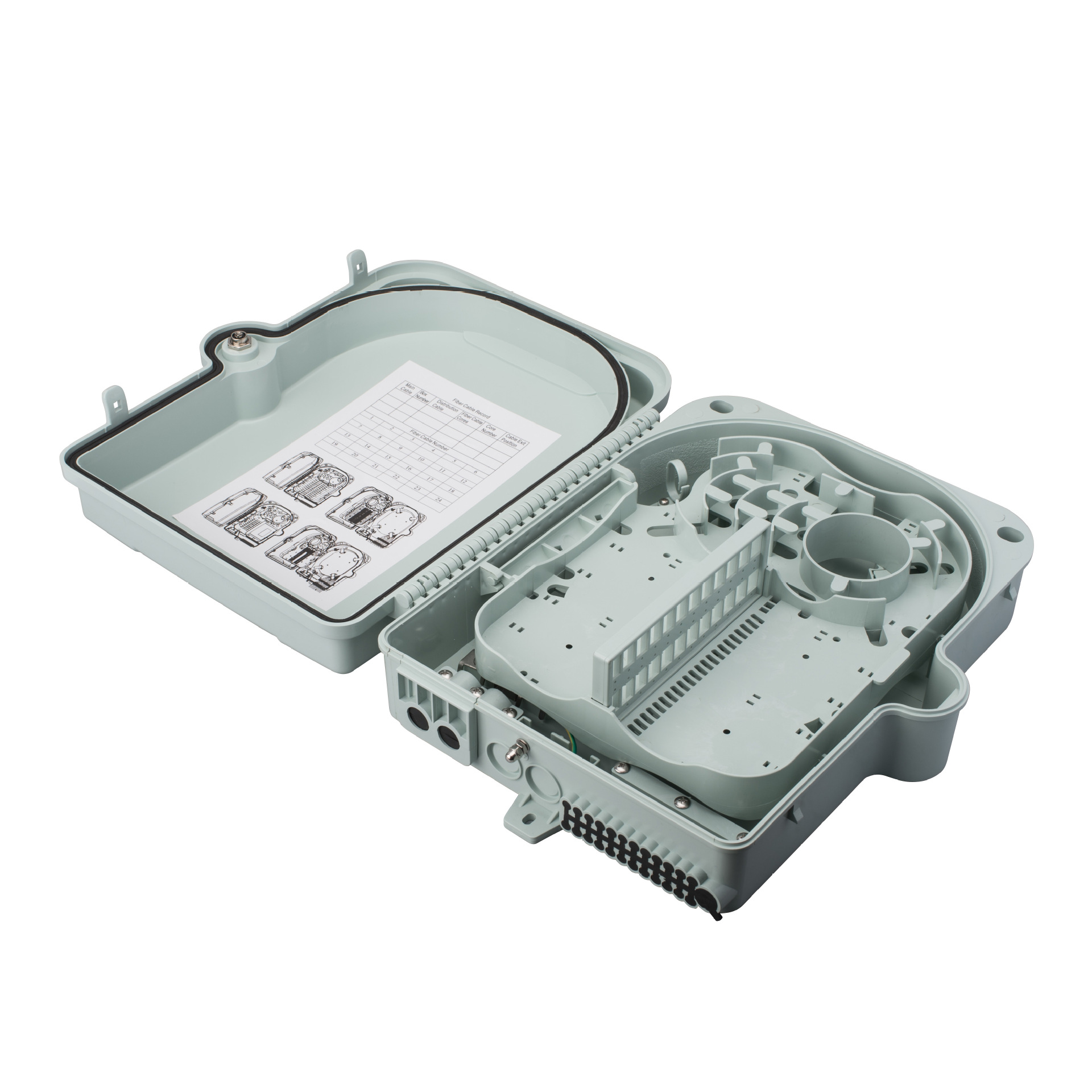
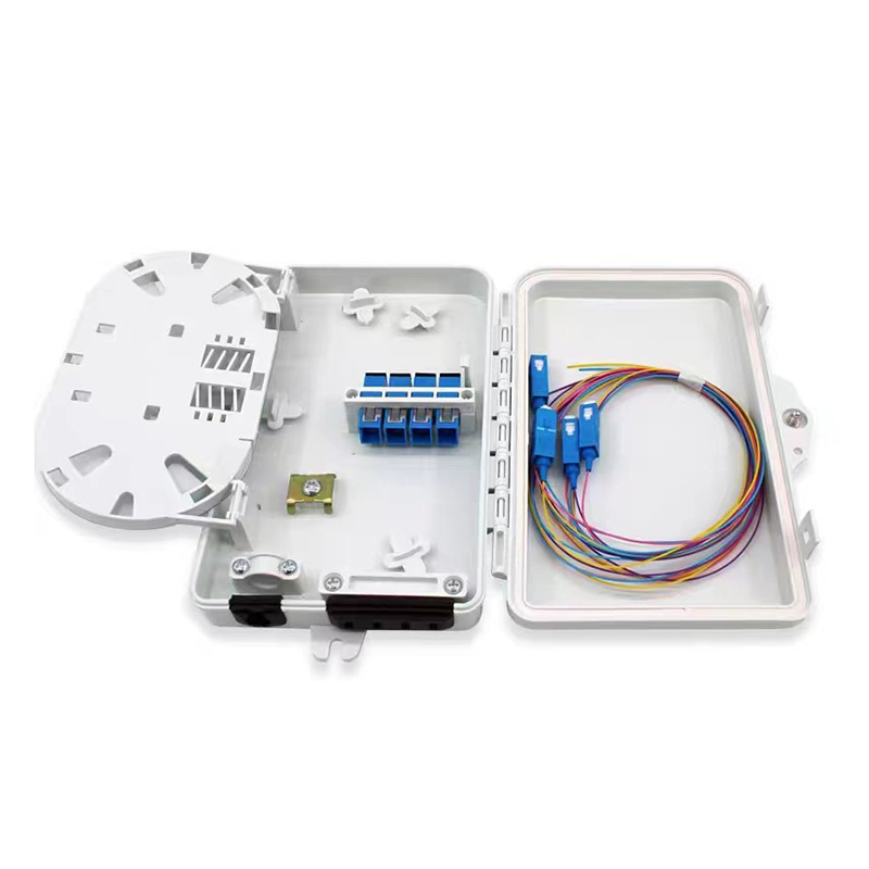
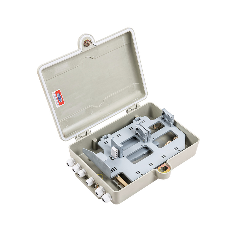
A fiber optic splitter terminal box combines fiber termination and optical splitting functions within a structured enclosure for FTTH and access network deployments. It can be configured with suitable PLC splitters, adapter interfaces, splice capacity, and cable management components according to project requirements. The enclosure provides an organized location for connecting feeder fibers with multiple distribution or subscriber lines while helping protect sensitive fiber connections. Depending on the installation environment, configurations can support wall-mounted, cabinet-based, or other distribution-point applications. Clear internal routing simplifies fiber identification, testing, and maintenance. For telecom operators, system integrators, and network contractors, a practical splitter terminal box can help streamline fiber distribution while supporting organized connections and future subscriber expansion.
Get A Quote

Case Study

Multi-Subscriber Fiber Splitting

A fiber optic splitter terminal box can distribute one incoming optical signal to multiple subscriber connections in FTTH networks. A suitable PLC splitter configuration can be selected according to the required split ratio and network architecture. Inside the enclosure, feeder fibers, splitter ports, and outgoing drop fibers can be organized to reduce cable congestion and simplify identification. This arrangement is useful for residential communities, apartment buildings, and other areas where multiple users share a common fiber distribution point. By combining splitting and termination functions, the box can reduce the need for separate connection locations and provide technicians with a more structured point for installation, testing, activation, and future service maintenance.

Building Fiber Distribution

In commercial buildings and multi-dwelling units, a fiber optic splitter terminal box can provide a centralized point for distributing optical signals to different floors, offices, or subscriber areas. The configuration can accommodate splitter modules, adapter interfaces, splice components, and cable entry requirements based on the network design. Organized internal routing helps technicians trace individual fiber paths when performing activation or troubleshooting work. Depending on available space, the enclosure can be installed at a telecom room, riser distribution point, or other designated network location. Capacity can also be planned around current connections and expected subscriber growth, supporting a more structured approach to building-level FTTH deployment.

Last-Mile Fiber Expansion

When an access network needs additional subscriber connections, a fiber optic splitter terminal box can provide a structured point for extending fiber distribution. The box can be configured with an appropriate splitter ratio, adapter arrangement, and fiber capacity according to the expansion plan. Feeder and distribution fibers can be routed separately to make connection identification and maintenance easier. This setup is useful when network operators need to add subscribers without redesigning the entire distribution structure. By providing a defined location for splitting, termination, and fiber management, the terminal box can support incremental FTTH expansion while keeping new connections organized and accessible for field technicians.

Related products

A fiber optic splitter terminal box is designed to combine optical signal splitting, fiber termination, and connection management within a compact distribution enclosure. It can be configured with PLC splitter modules, adapter panels, splice trays, and cable routing components according to the requirements of an FTTH or fiber access network. The box provides a defined transition point between incoming feeder fiber and multiple distribution or subscriber lines. Internal fiber management helps organize splitter connections and maintain appropriate routing around termination and splice areas. Depending on the installation, it can be used in residential communities, apartment buildings, commercial properties, telecom rooms, or outdoor distribution locations. Split ratios such as 1:4, 1:8, 1:16, or 1:32 can be considered based on the optical budget and network architecture. A suitable configuration helps simplify subscriber activation, fiber testing, troubleshooting, and future expansion while keeping the distribution point organized and serviceable.

Frequently Asked Questions

What is a fiber optic splitter terminal box?

It is an enclosure that combines optical splitting with fiber termination and management. It allows an incoming feeder fiber to be distributed to multiple output connections while providing organized space for adapters, splices, splitter modules, and fiber routing.
Depending on the network design, configurations may support splitter ratios such as 1:4, 1:8, 1:16, or 1:32. The appropriate ratio depends on subscriber requirements, optical loss, available power budget, and the overall PON architecture.
It can be used in FTTH distribution points, apartment buildings, telecom rooms, commercial properties, cabinets, and other access network locations. The enclosure and mounting method should be selected according to indoor or outdoor installation conditions.
Yes. A suitable configuration can include dedicated splice management components for fusion-spliced fibers. Splice capacity should be matched with the fiber count and splitter arrangement to maintain organized storage and convenient access during maintenance.
Consider splitter ratio, fiber capacity, connector type, adapter interface, splice requirements, cable entry method, mounting location, and future expansion. Optical loss and the network's power budget should also be evaluated when selecting the splitter configuration.

Related article

Data cables overall planning for office network construction.

12

Jun

Data cables overall planning for office network construction.

Practical Field Experience in Early Demand Assessment for Office Network Cabling When it comes to office network cabling, many business owners and project managers tend to focus solely on immediate connectivity needs and overlook long-term operati...
View More
Patch cord bending radius affects network performance.

17

Jun

Patch cord bending radius affects network performance.

Real-world cases showing the impact of improper bending on daily network operation Working in the structured cabling and network connectivity sector for over sixteen years, I have witnessed countless network faults traced back to unreasonable bend...
View More
Fiber Optic Cable Deployment for Data Center Backbone.

25

Jun

Fiber Optic Cable Deployment for Data Center Backbone.

Real-world Project Cases Reflecting the Value of Standardized Fiber Optic Cable Deployment With more than sixteen years working in structured cabling and data center infrastructure construction, I have taken charge of dozens of data center backbon...
View More
How to classify data cables by usage scenarios?

14

Jul

How to classify data cables by usage scenarios?

Real World Field Experiences with Multi Environment Network Deployments During a comprehensive network migration for a financial headquarters last spring, our deployment crew encountered major connectivity dropouts across different operational floo...
View More

Customer Testimonials

Ryan Mitchell

“The integrated splitter and termination layout helped us organize multiple subscriber lines in one distribution point. Installation was straightforward, and technicians found the fiber paths easier to identify during testing.”

Kevin Foster

“We used the terminal boxes for a residential fiber expansion. The organized internal routing made adding new connections easier while keeping existing subscriber fibers separated during maintenance.”

Get a Free Quote

Our representative will contact you soon.
Email
Mobile/WhatsApp
Name
Company Name
Message
0/1000
Integrated Fiber Splitting

Integrated Fiber Splitting

Combining optical splitting and fiber termination in one enclosure can simplify the physical structure of an FTTH distribution point. A suitable configuration can accommodate PLC splitter modules together with adapter interfaces, splice components, and fiber routing areas. This allows feeder fiber to enter a defined location and distribute optical signals to multiple downstream connections without requiring separate splitter and termination enclosures. The required split ratio can be selected according to subscriber density and network architecture. Integrating these functions can also make field installation more efficient by giving technicians a centralized location for splitter access, fiber termination, testing, and service maintenance. It is particularly practical for structured access network deployments.
Organized Fiber Management

Organized Fiber Management

Fiber management becomes increasingly important when one feeder connection serves multiple subscriber lines. The terminal box can provide dedicated routing and storage areas to help separate incoming fibers, splitter connections, and outgoing distribution cables. Proper organization helps reduce unnecessary fiber crossings and supports suitable bend-radius control around connection points. Adapter panels and splice components can be positioned according to the required network layout, making individual connections easier to identify during testing or troubleshooting. For installers and network operators, this structured arrangement can improve access to working fibers while reducing the chance of disturbing neighboring connections. It also provides a practical foundation for maintaining a clean and serviceable FTTH distribution point.
Flexible FTTH Expansion

Flexible FTTH Expansion

A configurable fiber optic splitter terminal box can support different FTTH deployment sizes and subscriber distribution requirements. Splitter ratio, fiber capacity, connector interface, and mounting method can be selected according to the application. The enclosure can be used in residential developments, multi-unit buildings, commercial facilities, telecom rooms, or designated distribution cabinets. When future subscriber growth is expected, additional capacity can be considered during the initial network design to reduce the need for major physical changes later. A centralized splitting and termination point also makes new connections easier to organize. This flexibility helps contractors and system integrators adapt the distribution structure to different project layouts and expansion plans.

Get a Free Quote

Our representative will contact you soon.
Email
Mobile/WhatsApp
Name
Company Name
Message
0/1000