Liquid to Liquid CDU: Separate Cooling Loops for AI & HPC

All Categories
Efficient Separation Between Facility and Technology Cooling Loops

Efficient Separation Between Facility and Technology Cooling Loops

A liquid to liquid coolant distribution unit transfers heat between two separate liquid circuits while maintaining controlled coolant flow and thermal conditions. This architecture is useful in data centers and high-performance computing environments where facility water and technology-side coolant require separation. The unit can use a heat exchanger to transfer thermal energy between the primary facility loop and the secondary IT cooling loop without directly mixing the two fluids. Depending on system requirements, it may incorporate pumps, valves, sensors, filtration, expansion components, manifolds, and control systems. Configuration can be matched to thermal load, flow rate, supply and return temperatures, pressure, coolant properties, and available installation space. This approach supports direct-to-chip cooling for AI servers, GPU platforms, HPC clusters, and other high-density computing infrastructure.
Get A Quote

Case Study

Facility Water Loop Separation

A high-density data center needed to connect its facility water infrastructure with a dedicated technology cooling loop while keeping the two fluids physically separated. A liquid to liquid coolant distribution unit was configured with a heat exchanger between the primary and secondary circuits. The system transferred heat from server-side coolant to the facility-side loop without direct fluid mixing. Pumps, valves, temperature sensors, and flow monitoring components could be integrated according to operating requirements. System planning considered rack thermal load, coolant flow, supply and return temperatures, pressure conditions, fluid compatibility, and heat exchanger capacity. This architecture provided a controlled interface for liquid-cooled server racks while helping isolate technology-side coolant conditions from facility water quality.

AI GPU Cooling Infrastructure

An AI computing facility was deploying GPU servers with direct-to-chip cooling and required an interface between the IT cooling loop and building-side infrastructure. A liquid to liquid coolant distribution unit connected the two circuits through a dedicated heat exchanger. The secondary loop supplied coolant to GPU cold plates through manifolds and quick disconnects, while the primary loop rejected the collected heat through facility equipment. Design considerations included GPU thermal load, secondary-loop flow rate, pressure drop, coolant chemistry, supply temperature, return temperature, and available installation space. Separating the circuits provided greater flexibility when selecting technology-side coolant conditions and allowed the AI cooling infrastructure to be managed independently from the facility-side water loop.

HPC Cooling System Upgrade

An HPC facility needed to introduce liquid cooling while maintaining its existing facility water system. A liquid to liquid coolant distribution unit was selected to create an isolated secondary cooling loop for high-performance computing equipment. The unit transferred heat through a liquid-to-liquid heat exchanger while circulating technology-side coolant toward CPU and GPU cold plates. The design incorporated supply and return manifolds, pumps, sensors, and control components according to the required operating conditions. Engineers evaluated total rack heat load, flow capacity, pressure limits, coolant compatibility, heat exchanger performance, and maintenance access. This approach allowed the HPC cooling system to use dedicated technology-side coolant while retaining the existing facility-side heat rejection infrastructure.

Related products

A liquid to liquid coolant distribution unit is designed to connect two separate liquid cooling circuits and transfer heat between them without directly mixing the fluids. A primary facility-side loop can provide heat rejection, while a secondary technology-side loop circulates coolant through cold plates serving CPUs, GPUs, and other high-power components. A heat exchanger forms the central thermal interface, while pumps, valves, manifolds, sensors, filters, and control components can be added according to system requirements. Important parameters include thermal load, primary and secondary flow rates, supply and return temperatures, pressure drop, coolant properties, heat exchanger capacity, and connection configuration. This architecture is suitable for AI data centers, HPC clusters, cloud infrastructure, telecom facilities, and other liquid-cooled computing environments. Separating the two circuits can provide greater control over technology-side coolant conditions while maintaining compatibility with facility-side cooling infrastructure.

Frequently Asked Questions

What is a liquid to liquid coolant distribution unit?

A liquid to liquid coolant distribution unit connects two separate liquid cooling circuits and transfers heat between them. A heat exchanger normally separates the primary facility-side loop from the secondary technology-side loop, allowing server coolant to be cooled without directly mixing it with facility water.
Separating the loops allows the technology-side coolant to be managed independently from facility water. This can help address differences in fluid quality, pressure, temperature, and chemistry. It also provides a controlled interface between data center liquid cooling equipment and the building's existing heat rejection infrastructure.
Yes. The secondary cooling loop can supply coolant to GPU or CPU cold plates used in AI servers. The CDU and heat exchanger should be sized according to GPU thermal load, flow requirements, supply and return temperatures, pressure conditions, coolant compatibility, and the number of connected servers or racks.
The heat exchanger transfers thermal energy from the technology-side coolant to the facility-side fluid while keeping the two liquids separated. Its required capacity depends on total heat load, flow rates, inlet and outlet temperatures, fluid properties, and the desired operating conditions of both cooling circuits.
Selection should consider thermal load, primary and secondary flow rates, supply and return temperatures, operating pressure, coolant chemistry, heat exchanger capacity, connection requirements, physical dimensions, and monitoring needs. For data centers, designers should also evaluate rack density, future expansion, facility water conditions, and maintenance access.

Related article

Connecting the World, Powering the Future

21

May

Connecting the World, Powering the Future

GLGW delivers high-quality cable solutions that keep the world connected. Built on trust and driven by innovation, our products provide reliable, efficient connectivity for industries, businesses, and communities. Experience the power of seamless connections and discover how GLGW is shaping a connected tomorrow.
View More
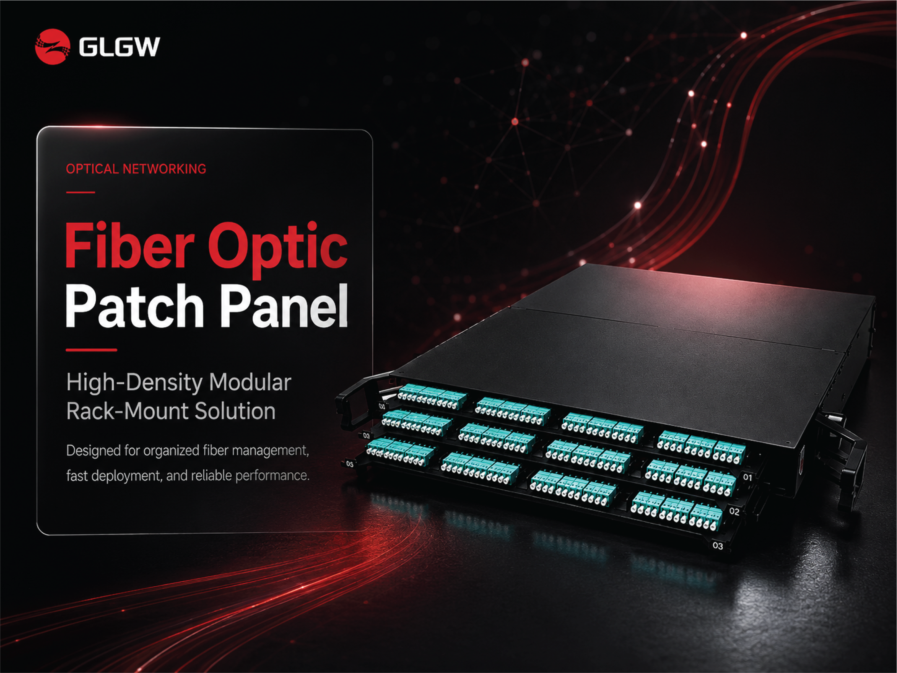
Fiber Optic Patch Panel: High-Density Modular Rack-Mount Solution for Reliable Network Management

21

May

Fiber Optic Patch Panel: High-Density Modular Rack-Mount Solution for Reliable Network Management

Discover how a high-density fiber optic patch panel improves cable organization, network reliability, scalability, and maintenance for data centers, telecom, FTTX, and enterprise networks.
View More
How to Strip Fiber Cable Without Damaging Fibers?

07

Aug

How to Strip Fiber Cable Without Damaging Fibers?

Stripping a fiber optic cable requires extreme precision. Because the glass cladding and core are extremely thin and fragile, even a microscopic scratch or nick can lead to severe signal loss (attenuation), microbends, or complete fiber failure und...
View More
Shielded structure improves anti-interference of data cables.

11

Sep

Shielded structure improves anti-interference of data cables.

Shielded Data Cable Explained: How It Prevents EMI and Improves Network Reliability What Is a Shielded Data Cable? A shielded data cable is a type of network cable designed with an additional conductive layer around the internal wires to protect da...
View More

Customer Testimonials

Daniel Morgan

The liquid-to-liquid configuration allowed us to maintain a separate technology cooling loop while using existing facility infrastructure. The heat exchanger and monitoring arrangement simplified system integration.

Kevin Turner

We connected several GPU cooling loops through a liquid-to-liquid CDU. Keeping the technology coolant separate gave our engineering team more flexibility when planning the rack cooling system.

Get a Free Quote

Our representative will contact you soon.
Email
Mobile/WhatsApp
Name
Company Name
Message
0/1000
Separated Cooling Circuits

Separated Cooling Circuits

A liquid to liquid coolant distribution unit creates a controlled interface between two independent cooling circuits. The primary loop typically connects to facility-side heat rejection equipment, while the secondary loop circulates technology coolant through server cold plates and rack distribution components. A heat exchanger transfers thermal energy between the fluids without allowing them to mix directly. This separation can be useful when the technology-side coolant requires different pressure, temperature, filtration, or fluid characteristics than the facility water. Depending on system requirements, pumps, valves, sensors, filters, and manifolds can be integrated into the CDU. The architecture provides a structured way to connect liquid-cooled IT equipment with existing or dedicated facility cooling infrastructure.
Direct-to-Chip Cooling Integration

Direct-to-Chip Cooling Integration

Liquid-to-liquid CDUs can support direct-to-chip cooling systems used for high-density CPUs, GPUs, and accelerators. The secondary loop supplies coolant to processor cold plates through manifolds, hoses, and quick disconnect couplings before returning warmed fluid to the CDU. The heat exchanger then transfers the collected thermal energy to the primary facility loop. System design can be configured around processor thermal load, secondary coolant flow, supply and return temperatures, pressure drop, and fluid compatibility. This arrangement provides a defined boundary between IT equipment and facility infrastructure. It is particularly useful for AI servers and HPC platforms where processor-level liquid cooling must operate reliably alongside larger building cooling systems.
Flexible Data Center Deployment

Flexible Data Center Deployment

A liquid to liquid coolant distribution unit can provide flexibility when integrating liquid cooling into new or existing data center infrastructure. The secondary technology loop can be designed specifically for server and rack requirements, while the primary loop remains connected to facility-side cooling equipment. This separation allows operators to evaluate technology coolant properties, flow conditions, temperature requirements, and pressure independently from building water conditions. The architecture can be deployed for individual high-density racks, AI clusters, HPC environments, or larger computing areas. Modular components such as manifolds, pumps, valves, sensors, and quick disconnects can support different installation layouts. Future cooling capacity can also be planned around additional servers, higher rack density, or expanded liquid-cooled infrastructure.

Get a Free Quote

Our representative will contact you soon.
Email
Mobile/WhatsApp
Name
Company Name
Message
0/1000